Since handing in my PHD thesis in March, I’ve been working as a Research Assistant (Post Doc) in MAGPIE. At first I was helping out others with their experiments and getting back into the flow of things, but yesterday I had the chance to try out some new hardware I’d made to do magnetic reconnection experiments.
The new hardware is significantly more flexible than the the previous version, and allows us to study reconnection in a variety of new regimes. But the important first test was whether it could reproduce the results in my thesis, and so I started with my standard configuration. The parts were mostly laser cut from 1.5 mm thick stainless steel, with the rest machined from stainless steel.
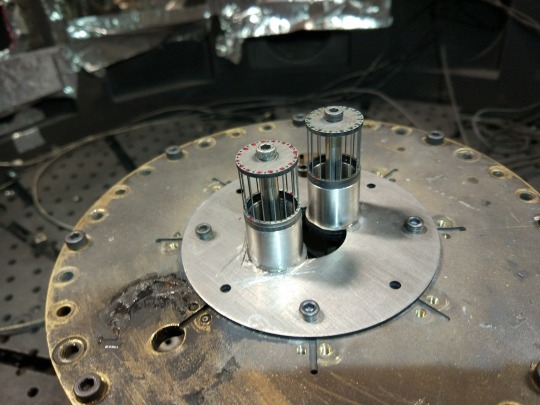
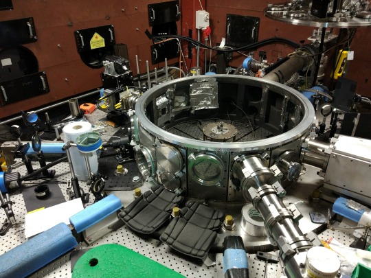
The final assembly looks like this…

…and in the next few images I’ll show how this was put together.
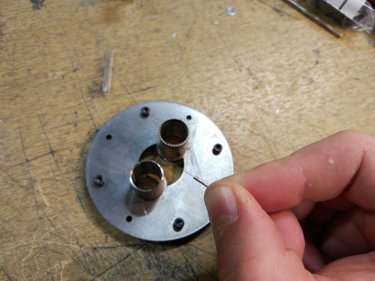
This is the anode plate, and it’s made from three laser cut sheets bolted together. Sitting on the anode plate are two thin cylinders, which have disks glued to the top which each have 32 small holes in for the carbon rods. Everything is glued together with superglue, but to avoid using too much glue I apply it a small drop at a time with a 200 micron acupuncture needle.
The cylinders then can be rotated to get them aligned:
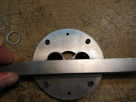
and the completed anode plate is then ready to go into the vacuum chamber. First, however, I need to install the cathode assembly.
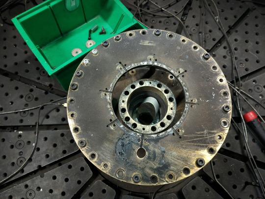
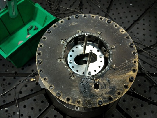
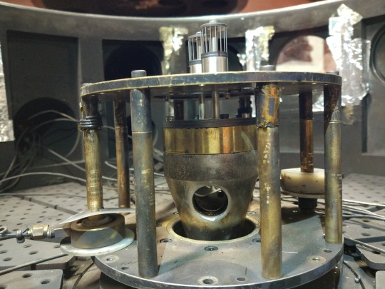
This image is taken from inside the vacuum chamber. The central object is the cathode, and the disk surrounding it is the cathode. The electrical current (one million Amperes!) flows from the anode to the cathode through whatever we put in the way. You can also see the elliptical mirror in the centre of the image which we use for reflecting a laser beam to take pictures of the plasma.
The cathode posts are bolted onto the cathode. These are long, stainless steel rods that are thick enough not be destroyed when the MAGPIE current passes through them.
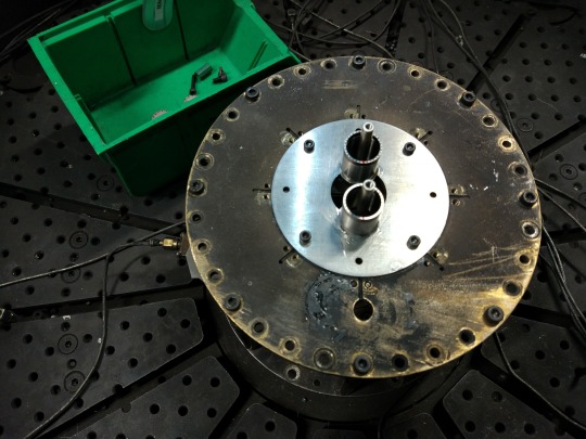
The anode assembly goes over these posts, and sits on the anode. The cathode posts go through the centre of the two cylinders on the cathode plate.
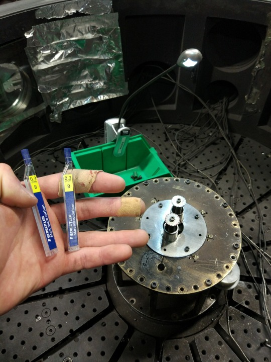
Now the top disks are attached, which also have 32 holes in each of them. I rotate the top disks so that the holes line up with the disks below, and then grab the carbon rods (aka pencil leads).
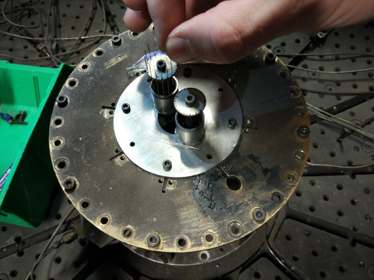
Each pencil lead is placed by hand, leaving some sticking out of the top.
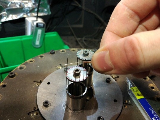
The excess pencil lead is removed by applying a small amount of pressure with an acupuncture needle. This breaks the lead just where it meets the top disks, leaving nothing sticking out of the top of the arrays. Nice and neat.
The completed arrays from below, showing the cathode and anode sections.
The array is built leaning over the chamber. The knee pads are vital as I get older and my joints start to go. It requires a good amount of core strength to keep myself from tipping forwards whilst building an array!
Finally, we put the lid on the vacuum chamber and pump out the air, ready for an experiment. The array takes about an hour to build, and is destroyed in a few billionths of a second. We can take pictures of the plasma using an expanded laser beam, and this is some of the data from the shot this morning:
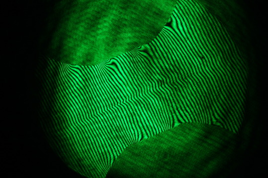
The dark and light fringes are caused by constructive and destructive interference of the laser beam, and the fringes shift wherever there is a large amount of plasma. You can find out more about this technique and the experiments I’ve been doing on MAGPIE in our recent paper (for free here, published in PRL) .