You’ve probably tried to capture the perfect photo of someone running or jumping, only to miss the action by a tenth of a second or so. When you’re blowing things up with a pulse of electrical current that lasts a few billionths of a second, taking an image at the right time becomes even trickier.
It is possible using cleverly designed circuits to time things like laser pulses and cameras to within a nanosecond, but these circuits are expensive, and prone to fail in exciting and unpredictable ways. However, the laws of physics tend to work quite well, and one of those laws is that the speed of light in a vacuum is constant – it won’t vary from one day to the next, and we can rely on it to stay the same.
Light moves at 300,000,000 metres per second in a vacuum. In air, it’s about the same speed, so light moves 30 cm, or about one foot in a billionth of a second (known as a nanosecond).
In MAGPIE we usually only have one laser to use in our experiments. Normally we fire a short burst of laser energy through the plasma, and take a picture of the light as it comes out the other side. It’s a bit like taking opening the shutter on a camera in the dark, and then firing a flash from the other side of the object you want to image. Even though the shutter is open for a long time, the only light that’s captured is when the flash goes off, and you image a silhouetted snapshot of the object at one moment in time.
But often we want to more than one image, maybe from different angles. And that’s where the speed of light comes in. Say we want to take two images, separated by 30 billionths of a second. The distance light travels in that time is 30*0.3 m, or 9 m. We would then split the laser pulse in two. Half the pulse goes through the plasma, and illuminates one camera. The other half gets bounced through 9 metres worth of extra mirrors, and then sent through the plasma, at another angle, to a different camera. Each camera is only illuminated by one laser beam at one time, so each has a snapshot of the plasma at just one instant.
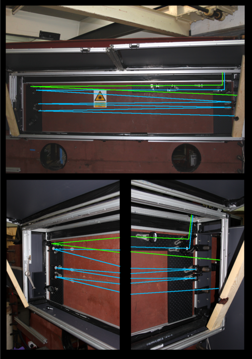
The image above is the optical setup we use to do this. I’ve drawn the path the laser beam takes in green (short path) and blue (longer path). You can see the blue beam bounces back and forth quite a few times before exiting out of the top. The beams enter from the left and exit towards the plasma at the top on the left. The top image is the full setup, and the bottom two images are the left and right set of mirrors.
We can play this trick with other instruments as well. We have a camera that takes pictures of ultra-violet light emitted by the plasma, which the human eye cannot see. The plasma glows so hot that instead of glowing red or even white, it glows in the ultraviolet. The camera looks like a circle, divided into quarters. When a quarter of the circle gets a pulse of current, it briefly converts UV light into visible light which a camera captures. If we want to take four images, separated by tens of nanoseconds, we want the four pulses of current to arrive at different times.
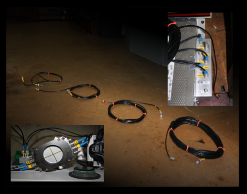
Now the pulse is of electricity, not light, so we can’t simply use mirrors. In fact, we can do something even easier – different lengths of cable. Electricity in these cables moves a bit slower than the speed of light, but it’s still at a predictable, constant speed. In the centre of the image above there are four lengths of cable, corresponding to a delay of 0 ns*, 10 ns, 20 ns and 90 ns from left to right. These cables join the pulse generator shown in the top right to the camera shown in the bottom left. The pulse generator emits on current pulse, which is split into four pulses which each travel down different lengths of cable, triggering the four quadrants of the camera at different times. When we look at the final image, we see four snapshots at different times – very useful for getting an idea of how the plasma changes.
All of the signals from the various instruments are fed back into our shielded room to some oscilloscopes.
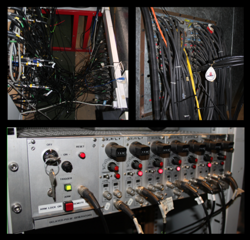
In the top right, the cables enter the shielded room. In the top left, the cables come from the wall of the shielded room to the back of the oscilloscopes. The bottom picture is of a delay generator – a complicated circuit that allows for fully adjustable delays without needing different lengths of cable! As you can see, the cabling looks like a bit of a mess, but there is a system of labelling that attempts to make it a bit more organised.
We’re fortunate we work on the nanosecond time scale. If we wanted to delay pulses by say a millionth or so of a second, we’d quickly find ourselves with cables hundreds of metres long. Fortunately, there are good circuits for slower delays like this, so it’s not really an issue. For shorter time scales (and some experiments out there look at millionths of billionths of seconds!) the cables would be very short, and mirrors have to be placed within a fraction of a millimetre – very fiddly!
We don’t often think about the speed of light day to day. There’s no point adjusting the length of your speaker cables to get the left and the right speaker playing at the same time – the human ear can’t detect such tiny changes in time. But at the timescale where it really begins to matter, we can exploit how ‘slow’ light is to channel it, like building dams and digging ditches to divert water from a stream on a beach.
*Obviously the 0 ns cable takes some time to traverse, but the cable has to have some length otherwise it couldn’t connect anything! The length of the 0 ns cable is added to the other cable lengths so they all delay the pulse by the right amount of time relative to the 0 ns cable.